Aggressive robot
Background & Concept
When I heard IEEE organised a “sumo robot competition”, I knew I wanted to participate. So I went ahead and built my robot. There are a few game rules, of which the most important is that you have to push the other robot out of the doyo without damaging it. And the robots mustn’t be controlled by a user, but do everything on its own.
One of the biggest questions I had is where and how to place the sensors. There are a lot of options
here: two at the front / one on each side / one rotating on a servo / … I watched
some videos and did some research and decided to go with the “two at the front”
approach, which works as follows: the robot spins around until it finds something
close enough to consider as a target. If one sensor measures a short distance and
the other a long, then the robot will spin until both sensors measure a short
distance, so the robot is always pointing at its target.
When looking online, I found that there are basically 3 cheap options for sensors: ultrasonic HC-SR04, infrared FC-51 or an infrared Sharp sensor. I bought the FC-51’s because I thought HC-SR04’s would interfere too much with each other and possibly with the enemy, but that didn’t work out for me. They are just completely unusable. Luckily, I had some HC-SR04’s lying around so I switched to them.
Components
- 4x DC motor + gearbox
- 4x Wheel
- 1x Battery pack Mr handsfree 5V USB output
- 1x Arduino USB Cable
- 1x Arduino Uno R3
- 2x HC-SR04 Ultrasonic sensor
- 2x 9V battery
- 2x 9V battery to wire adapter
- 4x MOSFET
- 2x 5V DPDT relay
- some resistors
- Wires & Soldering tools
- Case (see below)
Making the case
4 levels: 1 bottom with wheels, 1 with battery pack on it, 1 with arduino on it, 1 with batteries on it
This was going to be a small robot, so I knew I would have to build in height. I
also didn’t want to spend a lot of money on the case, so I decided it’d have to be
built in fablab, with 3mm thick 600x300mm MDF wood plates and lasercutters. So I went ahead and drew some inkscape files (see below). I went to fablab to get it all lasercutted
and glued the pieces together. It has many levels, each containing some components.
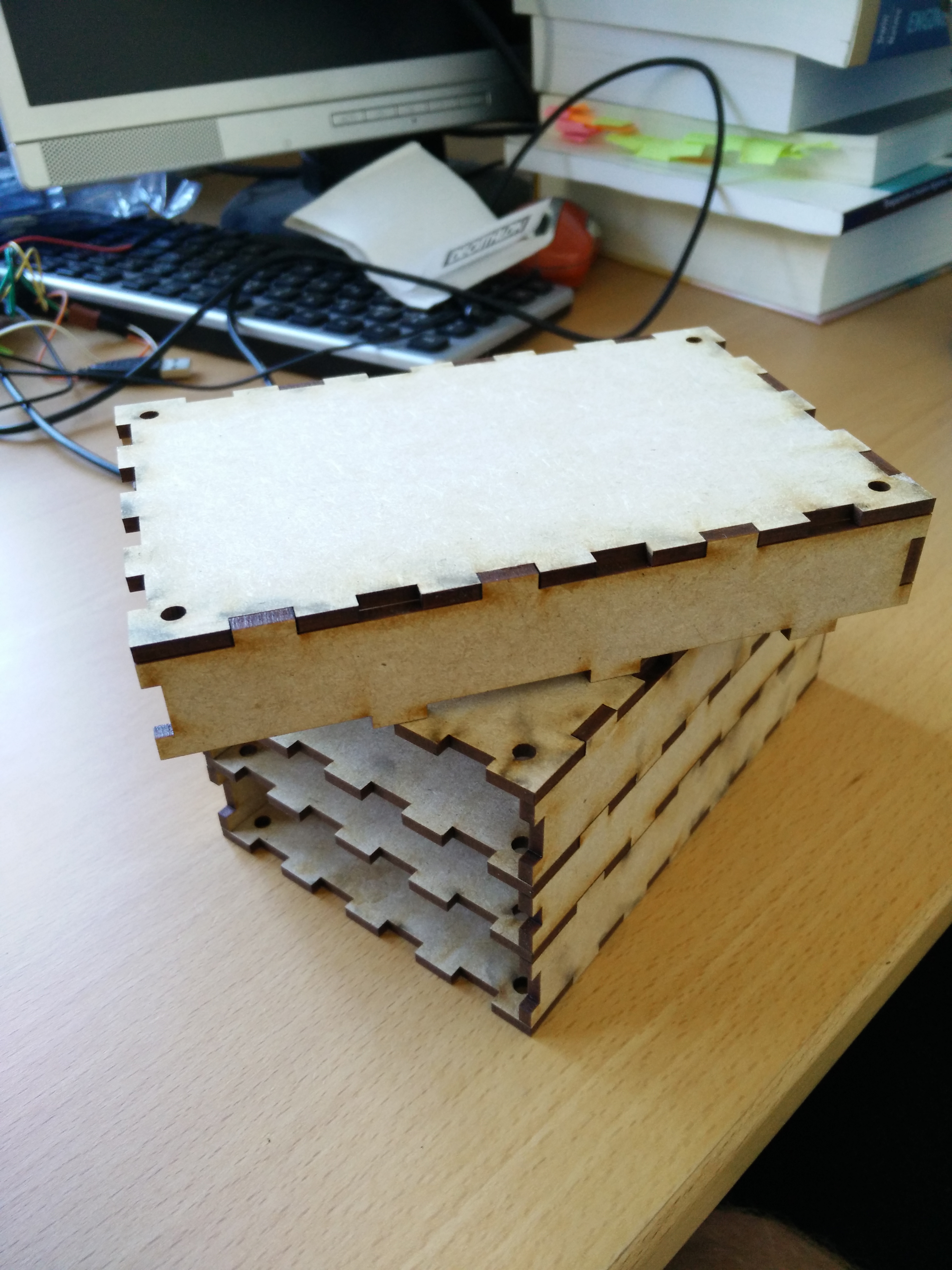
The multi-level case system I came up with
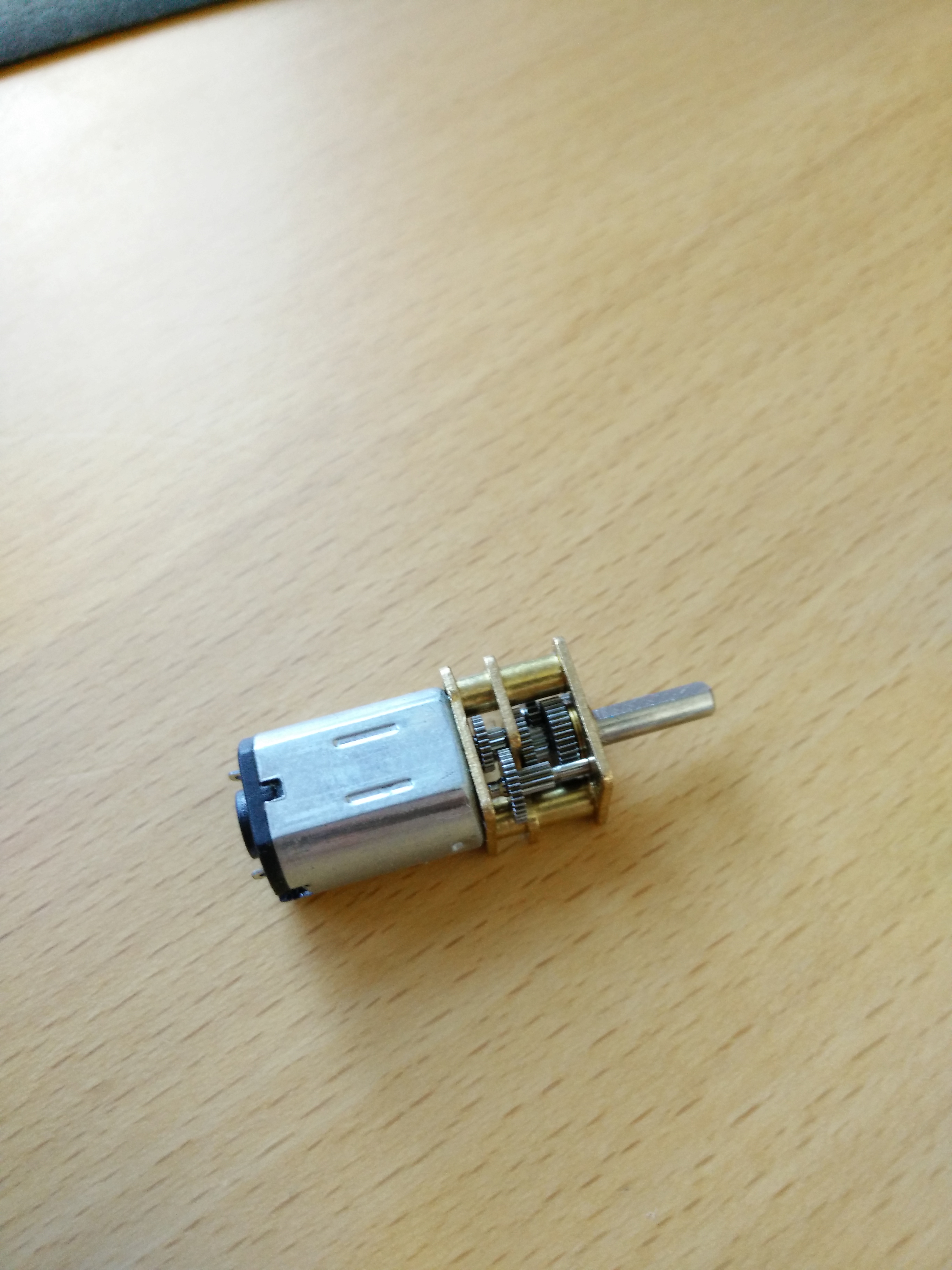
One of the motors with gearbox I'll be using
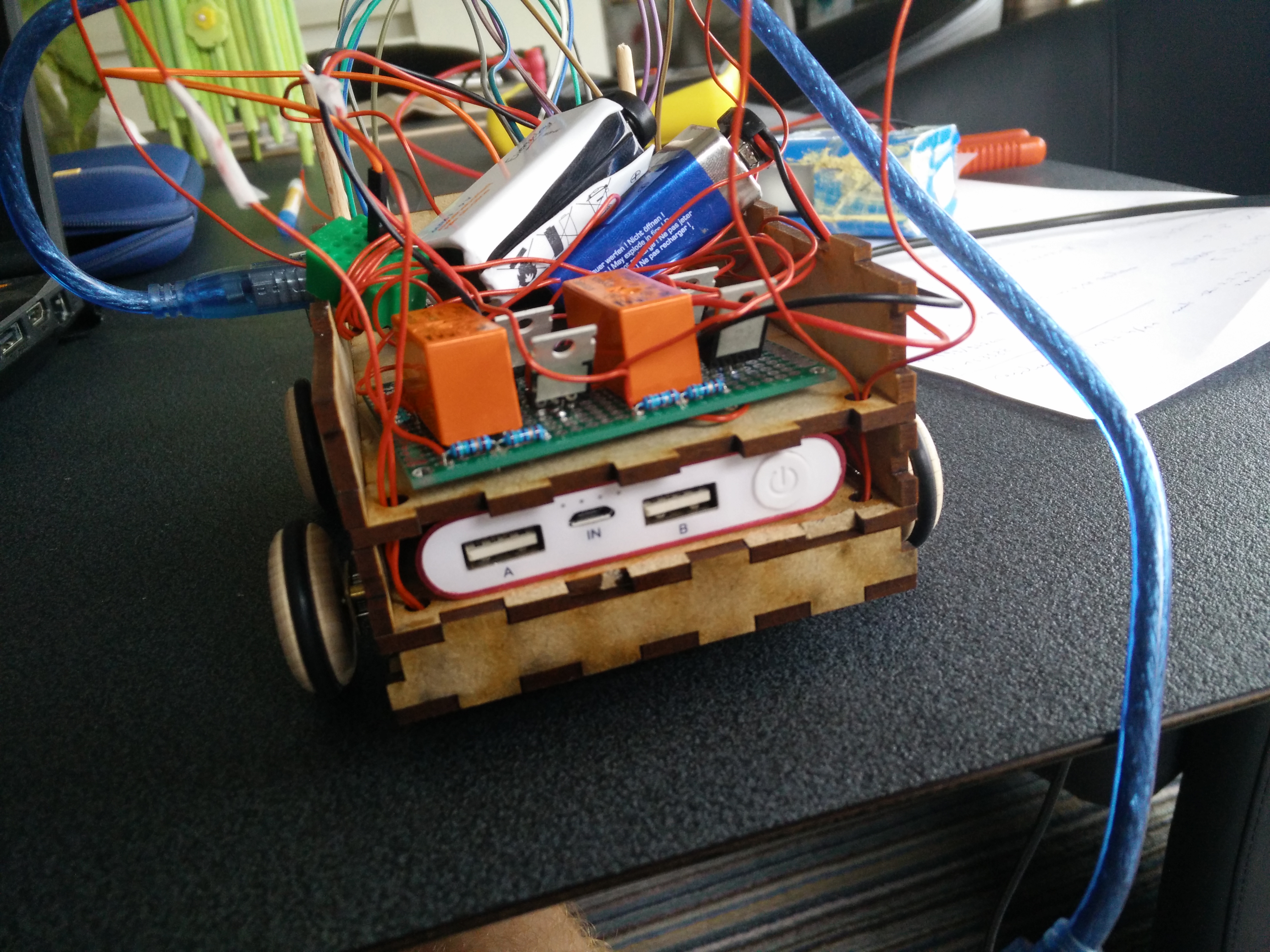
Finished mini cruizer
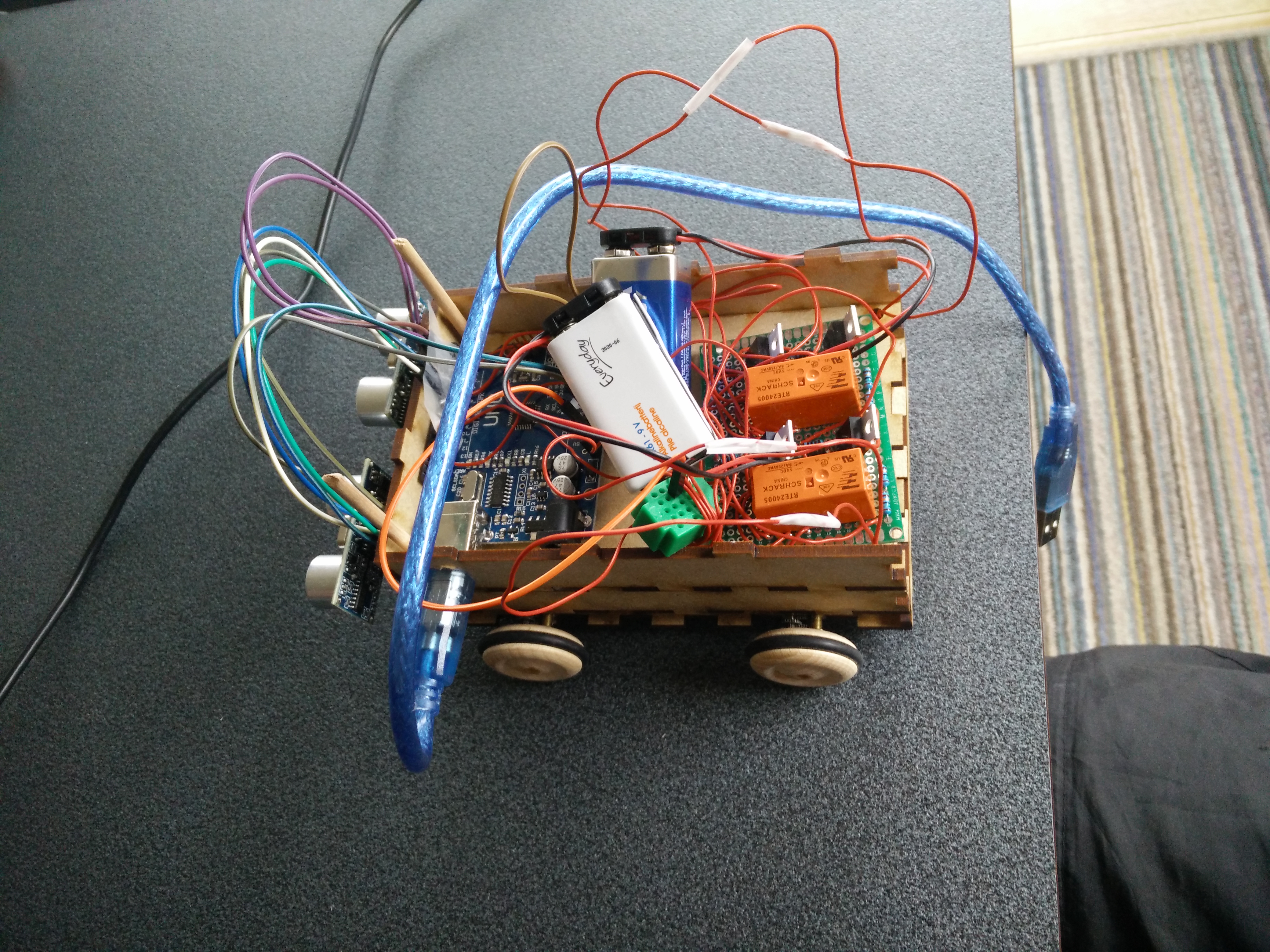
Isn't she beautiful?
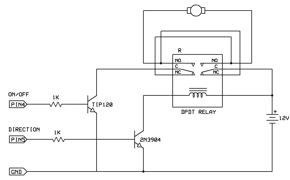
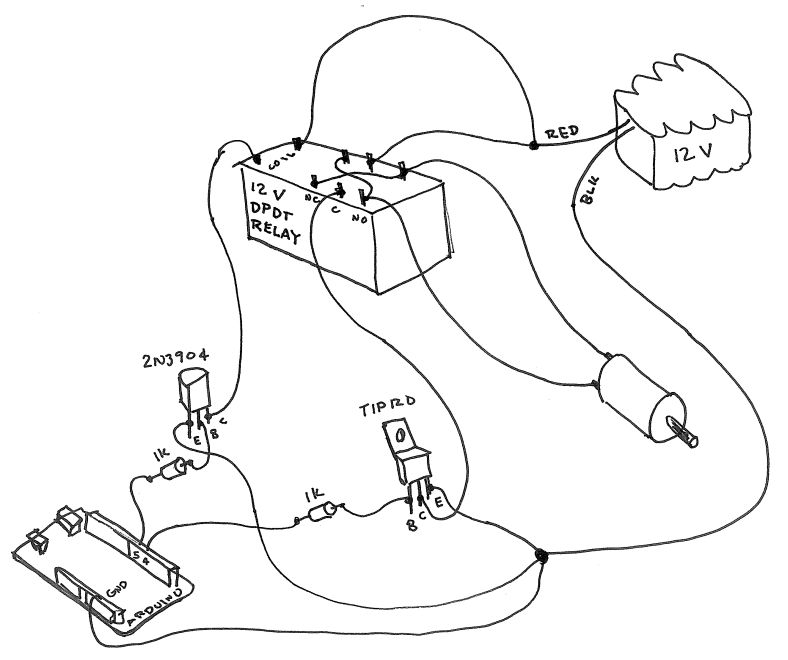
Electrical circuit
I got some nice circuit drawings from http://www.me.umn.edu/courses/me2011/arduino/technotes/dcmotors/bidirectional/bidirMotor.html
Competition
In the end, I teamed up with a friend of mine to participate in IEEE’s competition. We started over and built an entirely different robot. We put a lot more time and money in the project than I originally anticipated, but in the end we finished second so I’m really happy with that!
Programming
#include <NewPing.h>

#define TRIGGER_PIN  6
#define TRIGGER_PON 2
#define ECHO_PIN 7
#define ECHO_PON 3
#define MAX_DISTANCE 200

#define MOTORL 4
#define DIRL 5
#define MOTORR 8
#define DIRR 9

bool RFORWARD = HIGH;
bool RBACKWARDS = LOW;
bool LFORWARD = HIGH;
bool LBACKWARDS = LOW;

NewPing sonar(TRIGGER_PIN, ECHO_PIN, MAX_DISTANCE);
NewPing sonor(TRIGGER_PON, ECHO_PON, MAX_DISTANCE);


void setup() {
  Serial.begin(9600);
  int left = 200;
  int right = 200;
  pinMode(MOTORL,OUTPUT);
  pinMode(DIRL,OUTPUT);
  pinMode(MOTORR,OUTPUT);
  pinMode(DIRR,OUTPUT);
  pinMode(A4, OUTPUT);
  pinMode(A5, INPUT);
  digitalWrite(A4, HIGH);
  digitalWrite(DIRL,LFORWARD); //turn forward
  digitalWrite(MOTORL,LOW);
  digitalWrite(DIRR,RFORWARD); //turn forward
  digitalWrite(MOTORR,LOW);
}

void loop() {
  //add jumper between A4 and A5. Unplug to stop the robot.
  if (digitalRead(A5) == HIGH){
    unsigned int uS = sonar.ping();
    unsigned int oS = sonor.ping();
    int left = uS / US_ROUNDTRIP_CM;
    int right = oS / US_ROUNDTRIP_CM;

    if (left < 29 || right < 29){
      if (left > right){
        digitalWrite(DIRL,LBACKWARDS);
        digitalWrite(MOTORL,HIGH);
        digitalWrite(DIRR,RFORWARD);
        digitalWrite(MOTORR,HIGH);
        Serial.println("turning left");
        Serial.println(left);
        Serial.println(right);
      }
      else{
        digitalWrite(DIRL,LFORWARD);
        digitalWrite(MOTORL,HIGH);
        digitalWrite(DIRR,RBACKWARDS);
        digitalWrite(MOTORR,HIGH);
        Serial.println("turning right");
        Serial.println(left);
        Serial.println(right);
      }
    }

    else{
      digitalWrite(DIRL,LFORWARD);
      digitalWrite(MOTORL,HIGH);
      digitalWrite(DIRR,RFORWARD);
      digitalWrite(MOTORR,HIGH);
      Serial.println("full on");
      Serial.println(left);
      Serial.println(right);
    }

    delay(1000);

    digitalWrite(MOTORL,LOW);
    digitalWrite(MOTORR,LOW);

    delay(20);
  }

  else{
    digitalWrite(MOTORL, LOW);
    digitalWrite(MOTORR, LOW);
    Serial.println("Jumper unplugged.");
  }
Files
The .svg files to lasercut 3mm MDF plates: